



There is no single communication protocol that is best for every embedded system. The right choice starts from a much simpler question:
What do you want to connect, over what distance, at what speed, how many devices, and with what voltage levels and PCB constraints?
In a single project, all the interfaces may sit side by side: UART for debugging and the console, I²C for sensors, SPI for a Flash memory or display, and RS‑232 for talking to an industrial device or an old computer. The problem is that these names are sometimes treated as perfectly equivalent technologies, when they do not sit at the same level. The clearest example:
UART is not RS‑232.
UART describes an asynchronous serial transmit/receive mechanism inside the microcontroller or processor, whereas RS‑232 is an electrical and functional interface standard that uses voltage levels different from logic-level GPIO/UART signals and usually requires a transceiver.
The typical chain therefore consists of two distinct layers. The UART inside the microcontroller runs at the chip's 3.3 V logic, and this fragile digital signal does not reach the cable as is; it first passes through an RS-232 transceiver that converts it into a bipolar electrical signal compliant with the standard, which is what actually travels along the RS-232 cable to the other end. This separation between the logical role and the electrical role is what lets a single protocol run over different physical media, an idea we will return to repeatedly in this guide.
What Is a Communication Protocol in an Embedded System?
Inside an embedded system, we need an agreement between two or more devices on how to exchange data. This agreement may cover the shape of the electrical signal, the moment bits are read, whether a clock exists, bit order, how a device is selected, addressing, ACK/NACK signals, error detection, flow control, and the frame format.
But not every interface defines all these layers, and this is the source of much confusion:
| Interface | What It Defines |
|---|---|
| I²C | A two-wire bus with a clock, addresses, and ACK/Arbitration |
| SPI | A very simple synchronous bus, while many details of the device's commands come from its own datasheet |
| UART | Asynchronous framing, without defining on its own the line voltage or the connector |
| RS‑232 | Electrical and functional characteristics of the interface over a serial link |
Comparing the names without understanding which layer each interface belongs to can therefore lead to a flawed design.
Serial Does Not Always Mean the Same Thing
"Serial Communication" means bits travel one after another over a single line or a small number of lines, instead of many bits being sent in parallel. But serial interfaces differ fundamentally in how timing is handled.
In asynchronous communication, there is no shared clock line, as in UART, where both sides agree in advance on the baud rate and frame format. In synchronous communication, a clock drives the transfer timing, as in SPI and I²C. Having a clock simplifies determining the sampling instant, but it adds Signal Integrity constraints as speed rises or distance grows.
A Quick Comparison: UART, I²C, SPI, and RS-232
Before diving into each interface, the table below draws the overall picture:
| Property | UART | I²C | SPI | RS‑232 |
|---|---|---|---|---|
| Synchronization | Asynchronous | Synchronous | Synchronous | Often carries async UART/serial |
| Clock line | No | Yes, SCL | Yes, SCK | Not as a primary data line |
| Primary data lines | TX + RX | SDA + SCL | SCK + data + CS | TX/RX + GND, plus possible Handshake lines |
| Duplex | Usually Full duplex | Half-duplex logically on the bidirectional SDA | Usually Full duplex | Full duplex possible |
| Addressing | No | Yes | No unified Bus addressing; CS usually selects the device | Point-to-point |
| Multiple devices | Needs extra design | Natural | Possible with extra CS lines/other methods | Usually not on the same line |
| Speed | Depends on Hardware/Clock | Standardized modes up to several Mbit/s | No single universal limit; depends on the devices | Usually lower than local PCB interfaces |
| Typical use | Debug, modules, MCU↔MCU | Multiple Sensors/ICs | Flash, ADC, Displays | Industrial devices/Legacy/PC interfaces |
| PCB distance | Good at appropriate speeds | Often short due to capacitance | Often short | Designed more for cables |
| Signal level | CMOS/TTL depending on the device | CMOS/open-drain | Usually CMOS/push-pull | Positive/negative RS‑232 levels |
| Pull-ups | Usually no | Yes | Usually no | No |
| Clock polarity/phase | No | Not in the same way | CPOL/CPHA matter | No |
This is a conceptual comparison; do not replace the datasheet for your microcontroller, peripheral, board, and cable with generic "maximum" figures copied from tables on the internet.
UART: The Simplest Path Between Two Devices
Wiring and Timing
The Universal Asynchronous Receiver/Transmitter is a hardware block found in many microcontrollers and processors. In its simplest form it needs only three wires: device A's TX output connects to device B's RX input and vice versa, with a common GND between the two.
There is no clock line on the wire, so how does the receiver know the timing of each bit? The answer is that both sides agree in advance on a baud rate, with common values such as 9600, 115200, and one million bits per second, provided the hardware supports the chosen value within an acceptable error margin.
What Does a UART Frame Look Like?
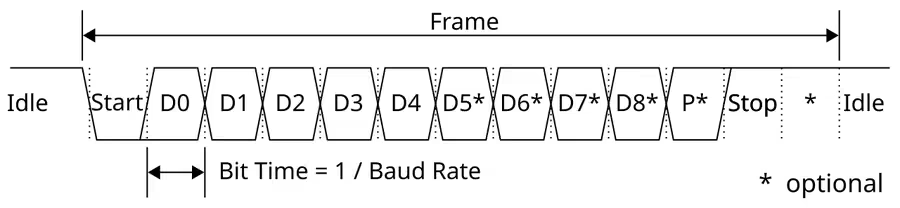
One of the most common settings is 115200 8N1, meaning 115200 baud, eight data bits, no parity, and one stop bit. The frame is read in time along a single line: the line starts in a high Idle state, then drops to the start bit, announcing the beginning of transmission and giving the receiver its synchronization point; it is immediately followed by the eight data bits, D0 through D7, read one after another at the agreed rhythm; and finally the line returns to the stop bit, ensuring a quiet gap before the next frame. In other settings, a Parity bit can be added between the data and the stop bit to detect simple transmission errors.
The Role of the Start and Stop Bits
Because the two sides do not share a clock on the wire, the receiver must detect the start of a character and then take samples according to the agreed baud rate. The start bit marks the beginning of the frame, and the stop bit provides the end, or the idle period required before the next frame. If the two sides' clocks differ by more than the receiver can tolerate, framing errors and corrupted bytes appear.
Parity: What It Does and What It Does Not
Parity adds a bit that can be used to detect some transmission errors, in its even and odd forms. But the popular claim that "parity guarantees no information is lost" is false; it detects only some error patterns, and it provides no error correction, no guarantee of delivery, no detection of all multi-bit errors, and no retransmission. If message integrity matters, the solution is a higher-level protocol that adds a CRC, a sequence number, an acknowledgment (ACK), a timeout, and retries.
Baud Rate or Bit Rate?
The two terms are not synonymous in communications generally: baud is the number of symbols per second, and bit rate is the number of bits per second. But in traditional UART, where each symbol represents a single bit value, the two numbers are roughly equal:
The actual payload, however, is smaller, because the frame carries start, stop, and parity bits. In an 8N1 setting, a single frame consists of:
So 115200 baud theoretically yields about:
and that is before any additional protocol on top.
Is 115200 the Maximum for UART?
No. 115200 is a historically common value, not a universal maximum. Some microcontrollers support much higher speeds, depending on the peripheral clock, the baud-rate divider, oversampling, clock accuracy, the PCB design, and the other side. So do not write in your design document that UART tops out at 115.2 kbps; read the datasheets for both sides.
UART Is Not Always 5V TTL
A common mistake is equating UART with TTL. More accurately, a UART peripheral may run at the chip's own I/O voltage, whether 1.8, 3.3, or 5 V. A 5 V UART must not be connected directly to an input that is not 5V-tolerant. So check VIH, VIL, VOH, VOL, and the Absolute Maximum Ratings, and you may need a Level Shifter between the two voltages.
Why UART Shines for Debugging
Because it is simple, needs no clock, works easily with a USB-to-UART adapter, suits console logs, and is easy to monitor with a logic analyzer. Its best-known example is a bring-up session on a new board: the microcontroller's UART connects to a small USB-UART bridge on the board, which appears to the computer as a virtual serial port, and the engineer opens a terminal on their laptop and sees log messages and command responses directly. That is why UART remains one of the first interfaces a firmware engineer reaches for when bringing any board to life: it is a simple diagnostic channel that needs neither a screen nor a network.
Its role goes beyond debugging, too: in our multi-link ground robot project, an HC-05 Bluetooth module connects to an Arduino UNO over UART to carry the wireless control commands to the robot. In our actual build of this project, wireless link stability and coordinating several electronic modules on one platform were among the main challenges — which is why understanding the UART layer itself is the first step in diagnosing any glitch in the commands.
When Is UART Not Suitable?
When you need several devices on one bus without extra hardware, very high bandwidth between ICs, clocked deterministic transfers, or built-in addressing. Then attention usually turns to I²C, SPI, or others.
RS‑232: Not Just UART at a Higher Voltage
Why the Confusion Persists
RS‑232 is a historical standard for point-to-point serial communication. The confusion with UART persists because many industrial systems use the same combination: UART frames as the logical protocol, and an RS-232 electrical transceiver as the physical medium carrying them over distances longer than 3.3 V logic can tolerate. Separating the two levels is essential for both understanding and troubleshooting; a frame-format problem is solved in the logical layer, a voltage-level or noise problem is solved in the electrical layer, and mixing them up wastes debugging time.
Voltage Levels on Each Side
The UART side may operate at two levels, 0 V and 3.3 V, while the RS‑232 side uses positive and negative levels, with the logic sense inverted compared with many UART circuits. According to standard RS‑232 explanations, logic 1 (Mark) is a negative voltage, logic 0 (Space) is a positive voltage, and there is an undefined region around zero in the receiver thresholds.
That is why you must never connect a UART pin directly to an RS‑232 connector; RS‑232 voltages can damage GPIO pins.
The Role of a MAX232-Class Transceiver
This transceiver performs two essential functions: converting voltage levels and inverting the signal as needed. The microcontroller's UART produces a 3.3 or 5 V logic signal, which the RS-232 transceiver picks up and converts into bipolar levels matching the standard, and this converted signal alone is what travels over the RS-232 cable to the other side. Some transceivers include a Charge Pump circuit that generates the required voltages from a single low supply, sparing the design a dedicated negative supply.
Connectors: Is DB‑25 Required?
No. The standard's history does include DB‑25, but DB‑9 is very common, and products may use other connectors; the standard is broader than a single connector shape. The simplest link needs only TX, RX, and GND, while other applications use Hardware Flow Control through the RTS and CTS lines.
DTE and DCE
RS‑232 was originally developed to connect DTE — Data Terminal Equipment to DCE — Data Communication Equipment, such as a terminal or computer to a modem, which historically shaped pin directions. But in modern embedded systems, what matters to you in practice may come down to specific questions: Who transmits on which pin? What is the connector pinout? Do we need a null-modem/crossover cable? Are RTS/CTS present? So do not rely on the "TX" label alone before checking the pinout.
RTS and CTS
In traditional hardware flow control, RTS means Request To Send and CTS means Clear To Send. But handshake implementation and pin functions may differ across hardware, drivers, and modern variants, so do not build a circuit from a generic drawing alone; consult the microcontroller's UART manual, the transceiver's datasheet, the other side's specifications, and the operating system's serial port settings.
Is RS‑232 Cable Length Fixed at 15 Meters?
It is not a hard rule. The specifications historically moved from a fixed length to electrical constraints such as capacitance, and the actual distance depends on cable capacitance, data rate, noise, grounding, the transceiver, and the environment. The engineering rule here:
The greater the distance or the industrial noise in the environment, the more you should also consider differential interfaces such as RS‑485 or CAN instead of pushing RS‑232 beyond its conditions.
I²C: Just Two Wires and Several Devices on One Bus
The Idea: Addresses Instead of Wires
The Inter-Integrated Circuit interface was developed by Philips Semiconductors, known today as NXP, and uses just two lines: SDA for serial data and SCL for the serial clock. Its essential advantage:
Multiple Targets can share the same Bus through Addresses.
On an I²C bus, the main controller connects to several devices over the same two wires and tells them apart by address, not by wiring: the temperature sensor answers at address 0x48, the EEPROM at 0x50, the RTC at 0x68, and the IMU at 0x6A. When the controller starts a read or write, it opens the frame with the target address, so all devices listen but only the addressed one responds. A complete system of sensors and memories can thus be built on just two wires, with a single controller as the clock source.
Why Does I²C Need Pull-up Resistors?
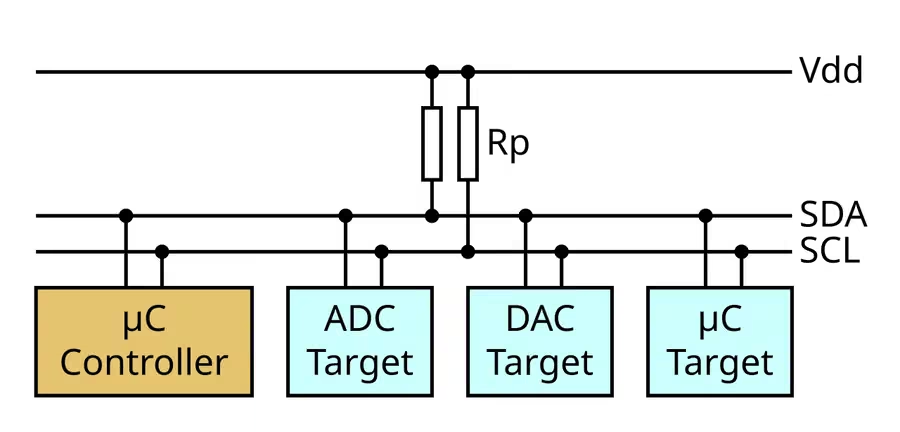
I²C lines traditionally operate with open-drain / open-collector behavior: a device pulls the line LOW but does not drive it HIGH in the usual way; instead, a pull-up resistor raises it when no device is pulling it.
Each I²C line thus rests on a pull-up resistor tying it to VDD, while any device on the bus can pull it to ground through an open-drain transistor. At rest, the line stays high thanks to the resistor, and when a device wants to signal, it pulls the line down explicitly. This arrangement is what lets several devices share a line without a direct push-pull conflict; if two devices try to pull at the same time, there is no short circuit between opposing polarities, they simply combine at a single low level, and conflict detection remains possible when a device on the line reads back a value other than the one it intended to put there.
Is the Pull-up Value Always 4.7 kΩ?
No. The value is determined by bus capacitance, supply voltage, I²C speed, rise-time requirements, and the devices' current-sinking capability. 4.7 kΩ is common in examples, but it is not a law. If the resistance is too large, rise time becomes slow; if it is too small, the current at LOW increases and may exceed the device's sinking capability.
Current I²C Speeds
According to NXP specification UM10204 Rev. 7, I²C modes are graded as follows:
| Mode | Maximum Speed |
|---|---|
| Standard-mode | 100 kbit/s |
| Fast-mode | 400 kbit/s |
| Fast-mode Plus | 1 Mbit/s |
| High-speed mode | 3.4 Mbit/s |
The specification also defines a unidirectional Ultra Fast-mode up to 5 Mbit/s, a different mode rather than a common substitute for traditional bidirectional use. So the old claim that I²C maxes out at 400 kbps is false as a general rule.
How Does an I²C Transaction Work?
In the simple model, the controller sends a START condition, then the address with the read/write (R/W) bit, the target replies with an ACK, and then data bytes follow, each followed by an ACK, until the transaction closes with a STOP condition. Beyond that, there are other mechanisms such as Repeated START, NACK, 7-bit or 10-bit addressing, multi-controller arbitration, and clock stretching in supported scenarios.
Does Philips Assign an Address to Every Device?
Not in that way. A device's address may be fixed in the datasheet, changeable through pins, software-configurable, or within a defined range, and some addresses are reserved for special purposes. So always ask when choosing several sensors of the same type: can you change the address? If three sensors share the same address with no way to change it, you may need an I²C multiplexer, a bus switch, several controllers, or a different interface.
ACK and NACK
After each byte comes an acknowledge phase, which helps determine whether the other side responded. But an ACK is not a CRC, not a guarantee of full payload integrity, not authentication, and not end-to-end confirmation. If the device is error-sensitive, check whether its own protocol provides a checksum, PEC, or CRC.
Multiple Controllers and Arbitration
I²C is not theoretically limited to a single controller; the specification supports multi-controller operation and uses arbitration to prevent data corruption when more than one controller tries to start at the same time. But not every microcontroller driver or RTOS stack handles every such scenario easily; supporting the standard does not mean it is easy to implement on your platform.
Clock Stretching
Some targets may hold SCL low to slow the controller when they need extra time. But in practice, not every controller implementation handles it the same way, some systems impose timeouts, and some devices do not use it at all, so check the datasheet instead of assuming the behavior.
Why Is I²C Length Limited in Practice?
There is no "one meter" that works as a rule for every I²C bus. The core challenge lies in bus capacitance, rise time, noise, pull-ups, topology, and speed. I²C was designed primarily for communication between ICs inside a device or on a board; stretched over a long cable, it may work under some conditions at low speeds with good design, but it becomes far more sensitive, and better solutions usually exist for long industrial cables.
SPI: Speed and Simplicity at the Cost of More Pins
Lines and Naming
The Serial Peripheral Interface is a synchronous bus that usually uses four lines: SCK for the clock, MOSI/SDO and MISO/SDI for data, and CS/SS for device selection. In traditional naming, MOSI means "Master Out Slave In" and MISO means "Master In Slave Out," while modern documents adopt functional names such as Host/Controller, Target/Peripheral, and SDO/SDI. The idea is the same in every case: a clock, a transmit line, a receive line, and device selection.
Why Is SPI Fast?
Unlike traditional I²C, SPI lines are usually push-pull, each direction has its own data line, and there is no unified address phase for every byte, so protocol overhead stays low. That is why it excels with components that need higher throughput, such as SPI NOR Flash, displays, ADC/DAC converters, high-rate sensors, FPGAs, and similar peripherals.
Is SPI's Maximum Speed 10 MHz?
There is no single universal value for SPI. Some devices run at 1 MHz, some at 10 MHz, and some at tens of megahertz or more, depending on the device, mode, and board. The real limit comes from the controller, the target, setup/hold timing, trace length, loading, voltage, signal integrity, and board layout. The important rule:
SPI speed is set by the slowest element in the link and the board's timing, not by the name SPI itself.
Full-Duplex Communication
Because there are two separate lines, one from the controller to the peripheral and one in the opposite direction, bits can move in both directions within the same clock cycle. But this does not mean the application protocol always benefits; many chips use a transaction in which the controller first sends a command or address and then receives data, so the link is electrically full duplex while actual use looks logically half-duplex.
Multiple Targets on SPI
Older sources may describe SPI as point-to-point, but it is very common for several devices to share the SCK, MOSI, and MISO lines while each gets its own select line: CS0 for the Flash, CS1 for the ADC, and CS2 for the display.
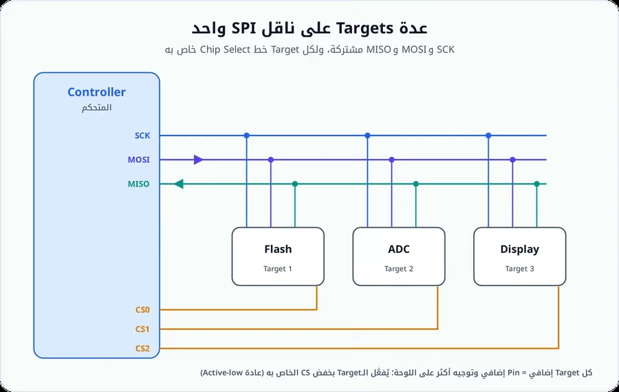
The problem is that each target traditionally needs its own chip select, so the more devices there are, the more pins, routing, and firmware management complexity. This is where I²C may suit many low-data sensors better.
CPOL and CPHA: SPI's Famous Trap
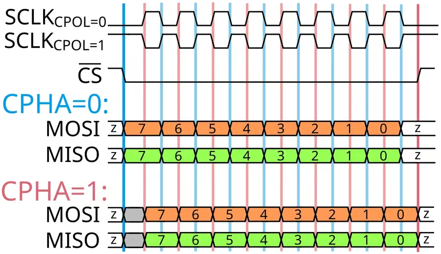
SPI has modes that depend on clock polarity (CPOL) and clock phase (CPHA), giving four common modes: Mode 0, Mode 1, Mode 2, and Mode 3. If the controller and the target do not agree on the mode, you will see the clock and data on the lines, but the bytes will be wrong. That is why the first thing to check when SPI does not work is:
CPOL/CPHA + bit order + CS timing.
SPI Has No ACK or Addressing
Unlike I²C, basic SPI offers no unified bus-level acknowledgment or addressing; instead, each chip has its own command protocol in its datasheet. A Flash memory, for example, might use the following commands:
| Command | Function |
|---|---|
| 0x03 | Read |
| 0x02 | Page Program |
| 0x9F | Read JEDEC ID |
while another sensor uses completely different commands. The takeaway:
"SPI" tells you how the bits move, but not necessarily what the bytes mean.
Head-to-Head Comparisons
UART or SPI?
| Choose UART When | Choose SPI When |
|---|---|
| The link is between just two devices | The peripheral is on the same PCB |
| You need a debug console | You need high throughput |
| You are working with a modem, GNSS, or Bluetooth module | You are working with Flash, a display, or an ADC |
| You do not want a clock line | The extra pins are acceptable |
| The data volume is not huge | You can control clock timing precisely |
| You need a simple cable within suitable electrical levels |
I²C or SPI? The Most Famous Comparison
I²C is usually better when there are several sensors, you want only two wires, the required bandwidth is moderate or low, and addressing is useful. SPI is better when speed matters more, the number of devices is small, latency is low, full-duplex communication is useful, and pins are available.
There is nothing wrong with using both in the same project. A typical Sensor Hub board might put the temperature and humidity sensors and the RTC on I²C, while putting a high-speed IMU, Flash memory, and the display on SPI.
UART or RS‑232? The Right Comparison
The question "UART or RS‑232?" partly resembles another: "Do I want a frame format or an electrical layer for the cable?" A UART from the microcontroller can be converted to RS‑232, to RS‑485, to USB through a bridge, or used directly at logic levels. So RS‑232 is not a direct competitor to UART in every case.
How Do You Choose the Protocol?
The Decision Path
Start with a first question: is the other end on the same PCB?
If the answer is yes, the next question is the number of devices. One or two devices with high throughput point you to SPI, several sensors with few pins point you to I²C, and a simple module or a debugging need points you to UART.
If there is a cable, the question becomes distance and noise. A short distance in a quiet environment may allow logic-level UART depending on the design, legacy or industrial point-to-point equipment may suit RS‑232, and longer distances, noisy environments, and multi-drop links call for also looking at RS‑485 or CAN.
Do Not Choose by Speed Alone
Speed is one criterion among far more important ones, collected in the table below:
| Criterion | What It Means in Practice |
|---|---|
| Number of devices | I²C is excellent for many devices, SPI usually needs a CS per device, and UART is usually point-to-point |
| Pins | With a small microcontroller, I²C saves pins, while SPI may consume several chip selects |
| Bandwidth | Displays and Flash usually go to SPI, while a temperature sensor is often fine on I²C |
| Latency | SPI is direct and fast, I²C carries address and ACK overhead, and UART carries start/stop framing |
| Power | Do not judge by the protocol name; it depends on frequency, pull-ups, duty cycle, sleep modes, and the peripheral implementation |
| Software ecosystem | Is there a driver? Does Linux or the RTOS support it? Is the SDK mature? Is DMA available? |
| Debuggability | UART is usually the easiest for manual debugging, while I²C and SPI often need a logic analyzer to understand timing |
| EMI and signal integrity | A fast clock combined with long traces can cause problems |
The Electrical Layer Matters More Than the Protocol Name
Check the Voltage Before Connecting
Before connecting any two devices, check the supply voltage VDD, the VIH/VIL thresholds, the output type, 5 V tolerance, the pull-ups, and the absolute maximum ratings. Take a microcontroller running at 1.8 V and an I²C sensor running at 3.3 V: even if both are "I²C," you may need a bidirectional level shifter depending on the thresholds and circuitry. A compatible protocol does not mean compatible voltages.
Open-Drain Versus Push-Pull
| Style | Where It Is Used | Characteristics |
|---|---|---|
| Open-drain + Pull-up | I²C | Several devices share the line, rise time is RC-limited, and wired arbitration is possible |
| Push-pull | Usually SPI and UART | Faster edges, direct HIGH and LOW drive, and two opposing outputs must not be tied together without proper design |
These electrical differences explain much of the variation in speed and topology between the interfaces.
Debugging and Signal Integrity
Why Does It Work on a Breadboard, Then Fail in the Product?
SPI may work at 20 MHz on short wires and then fail with a ribbon cable. The problem is not always the firmware; it may be ringing, overshoot, crosstalk, ground bounce, a poor return path, long stubs, or impedance discontinuities.
Symptoms of SPI Problems
Signs include bits changing randomly when the clock is raised, a link that works at 1 MHz but fails at 20 MHz, an occasionally wrong Flash ID, and a first byte that arrives correctly while the rest are corrupted. Solutions may include shorter traces, a better ground return path, a lower clock, a series resistor near the driver, a better board layout, and measurement with a scope.
Symptoms of I²C Problems
Signs include SDA rising slowly to HIGH, the bus getting stuck LOW, random NACKs, and a bus that works with one sensor but fails when another is added. Then check the pull-up resistance, capacitance, address conflicts, voltage, clock stretching, and topology.
The Logic Analyzer: An Indispensable Tool
A logic analyzer can decode UART, I²C, and SPI instead of leaving you to stare at the raw waveform. In an I²C transaction, for example, it might show: START, then address 0x68 with W and ACK, then 0x1B with ACK, then 0x00 with ACK, then STOP. From a reading like this you can immediately spot a wrong address, a NACK, a missing STOP, or a wrong register.
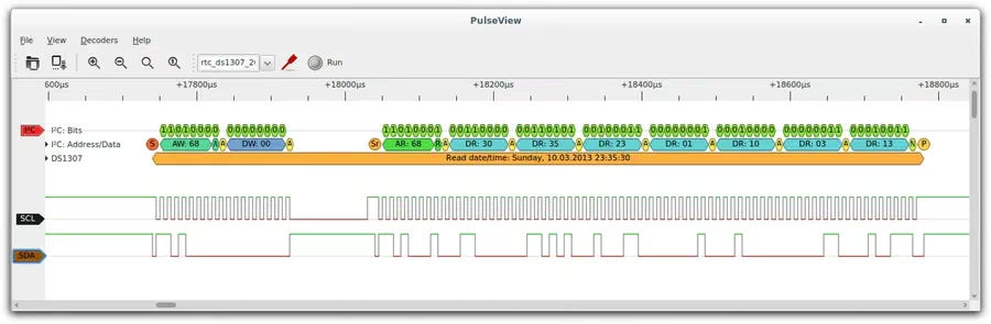
But a logic analyzer does not always reveal analog edge-quality problems, so for electrical issues, use an oscilloscope.
Logic Analyzer or Oscilloscope?
| Tool | Excels At |
|---|---|
| Logic Analyzer | Decoding bytes, long captures, protocol sequence, and logic timing |
| Oscilloscope | Rise/fall time, overshoot, ringing, noise, and voltage thresholds |
The best debugging sessions sometimes use both tools together.
Common Design Mistakes
| Mistake | Consequence or Correction |
|---|---|
| Connecting UART directly to RS‑232 | The input may be damaged, or the link fails because of voltage levels |
| I²C without pull-ups | The lines will not work as expected |
| An unsuitable pull-up | Slow rise time or high current |
| The wrong SPI mode | CPOL/CPHA mismatch |
| Assuming a fixed protocol speed | There is no "SPI = 10 MHz" or "UART = 115200 max" as a law |
| No shared ground on a logic-level interface | Many single-ended links need a common reference |
| Connecting two different voltages | Protocol-compatible ≠ electrically compatible |
| The same I²C address on two devices | A bus conflict at the response level |
| Cable length without calculation | A bus designed for a board may not suit a long run |
| Parity as a substitute for CRC | Parity is not comprehensive message protection |
Beyond the Four Interfaces: RS‑485, CAN, USB, and I3C
RS‑485
When designing an industrial system, a vehicle, or a long cable run, do not limit yourself to the four protocols. RS‑485 is useful when we need differential signaling, longer distance, multi-drop links, and greater noise tolerance. But it mainly defines the electrical layer, and may need a higher protocol such as Modbus RTU.
CAN
CAN suits cases that need a multi-node bus, arbitration, and error detection, in industrial environments or vehicles. Choosing among UART/I²C/SPI/RS‑232 is not always the complete list.
USB
To connect a modern product to a computer, USB may be better than native RS‑232. But what looks like a serial port from the outside may be something entirely different on the inside: the microcontroller's UART connects to a USB-UART bridge that converts the frame stream into USB packets, and the computer on the other end sees a Virtual COM Port that it treats as an ordinary serial port, while the physical transfer runs over the USB bus at its own speed and with its own protocol. This is another example of why separating layers matters: a single logical protocol may travel inside entirely different physical media.
I3C: The Modern Direction
As sensor counts grew, the need emerged for a bus that keeps I²C's simplicity while offering newer performance and features, so MIPI developed I3C, and the current editions as of 2025 are MIPI I3C v1.2 and MIPI I3C Basic v1.2.
I3C uses a two-wire interface and offers dynamic addressing, in-band interrupts, higher performance, and better power management, with the ability to coexist with a number of legacy I²C devices on the same bus under supported conditions. MIPI describes I3C as a successor to I²C in certain classes of applications rather than an immediate replacement, and cites a typical rate of 11.1 Mbit/s, with High Data Rate modes reaching about 100 Mbit/s in supported options.
Will I3C Replace SPI?
Not necessarily. SPI remains excellent when we need a simple data path, high throughput, and a broad ecosystem of Flash memories, displays, and peripherals. I3C targets especially the improvement of control and sensor buses, reducing pins and power, with advanced management features. A single project may combine I3C for sensors, SPI for Flash, and UART for debugging.
Modern Terminology: Controller and Target
Older documents use the terms Master and Slave, while many modern documents and standards are moving to terms that describe function more clearly, such as Controller/Target, Host/Client, and Peripheral. In this article we use Controller/Target wherever possible, mentioning the older terms only when they help in reading older datasheets.
Real Performance: Do Not Rely on Clock Frequency Alone
If SPI runs at 20 MHz, that does not always mean an actual payload of 20 Mbit/s. A transaction may contain a command, an address, dummy cycles, gaps between chip-select assertions, and other protocol overhead. Likewise, I²C carries START, the address, the R/W bit, ACK, and STOP, and UART carries start, stop, and parity bits. So measure the effective application throughput, not the clock alone.
Worked Examples
The selection method becomes clear when applied to concrete cases:
| Example | Requirements | The Logical Choice |
|---|---|---|
| Temperature sensor | 2 bytes per second, several sensors, speed unimportant, few pins | Usually I²C |
| External NOR Flash | Reading large blocks, speed, limited number of devices | An SPI/QSPI-class interface depending on the device |
| GPS/GNSS module | Periodic text or binary messages, a direct link, easy debugging | Usually UART |
| Legacy industrial measuring device | A cable, an existing port, point-to-point, compatibility over speed | RS‑232 may fit |
| Dozens of modern sensors | Two wires, dynamic addressing, in-band interrupts, more bandwidth than traditional I²C | I3C if the platform and devices support it |
A Practical Selection Matrix
| Need | The Option to Start Examining |
|---|---|
| Debug Console | UART |
| A simple Sensor | I²C |
| Multiple Sensors on two lines | I²C / I3C |
| High-speed Flash | SPI |
| Display | SPI |
| High-data ADC | SPI |
| Simple MCU↔Module | UART |
| Legacy industrial point-to-point | RS‑232 |
| Long noisy Cable | Often RS‑485 / CAN |
| Automotive multi-node | CAN / LIN depending on requirements |
| Modern sensor aggregation | I3C where support is available |
This matrix is not a final verdict; the datasheets and the requirements are the deciding factor.
Checklists
Before Choosing the Interface
Write down the following values for your project, then compare the options against them:
| Item | What to Write Down |
|---|---|
| Number of devices | How many devices |
| Required payload bandwidth | The payload bandwidth needed |
| Maximum latency | The maximum acceptable latency |
| Cable/trace length | The length of the cable or trace |
| Supply voltages | The supply voltages |
| Available GPIO pins | The pins available |
| Need addressing? | Whether you need addressing |
| Need full duplex? | Whether you need full-duplex communication |
| Need hot-plug? | Whether you need to connect while powered |
| Noise environment | The noise environment |
| Power budget | The power budget |
| MCU peripheral availability | The peripherals available on the microcontroller |
| DMA required? | Whether you need DMA |
| OS/driver support | Operating system and driver support |
| Expected product lifetime | The product's expected lifetime |
Before Powering the First Prototype
| Interface | What to Verify |
|---|---|
| UART | TX ↔ RX crossed correctly, ground shared, both sides agree on baud, data bits, parity, and stop bits, voltages compatible, and no RS‑232 voltage present by accident |
| I²C | SDA/SCL wired correctly, pull-ups installed and tied to the correct voltage, address correct and conflict-free, bus speed supported by every device, and rise time acceptable |
| SPI | SCK, MOSI/SDO, MISO/SDI, and the CS pin wired correctly, CPOL, CPHA, and bit order correct, maximum SCK within the target's timing, and CS setup/hold timing respected |
| RS‑232 | A transceiver sits between the logic UART and the cable, the TX/RX pinout is checked, DTE/DCE assumptions are checked, RTS/CTS are configured if needed, and the connector pinout is verified |
Security: These Interfaces Do Not Encrypt Your Data Automatically
UART, I²C, SPI, and RS‑232 are not security protocols. If an attacker can physically reach a UART debug header, an SPI flash, or an I²C bus, they may be able to read data, capture the firmware, send commands, and tamper with peripherals.
That is why sensitive products should close debug interfaces in production as needed, use Secure Boot, enable Flash protection, verify firmware signatures, avoid storing secrets as plain text in external memory, and establish a Threat Model for physical access.
Conclusion
The choice between UART, I²C, SPI, and RS‑232 is not settled by a single speed table, but by understanding each interface as a different tool for a different purpose:
| Interface | Its Essence | Best Uses |
|---|---|---|
| UART | A simple, asynchronous serial link | Debugging and modules |
| I²C | A two-wire bus with addressing | Sensors and multiple devices on a PCB |
| SPI | A fast, low-overhead synchronous bus | Memory, displays, and high-data components |
| RS‑232 | A point-to-point electrical interface, usually needing a transceiver between the logic UART and the line | Cables and legacy and industrial systems |
| I3C | A modern evolution of sensor and control buses combining a two-wire architecture with dynamic addressing | Modern sensor aggregation with advanced performance and management features |
So instead of asking "Which protocol is faster?", ask:
What is the least complex interface that meets the required bandwidth, distance, device count, power, and reliability within the design's actual electrical constraints?
Sources and References
NXP Semiconductors — UM10204, I2C-bus specification and user manual, Rev. 7.0
https://www.nxp.com/docs/en/user-guide/UM10204.pdfMIPI Alliance — I3C and I3C Basic
https://www.mipi.org/specifications/i3c-sensor-specificationMIPI Alliance — I3C Basic v1.2
https://www.mipi.org/mipi-i3c-basic-downloadMicrochip — SPI Mode Overview
https://onlinedocs.microchip.com/Texas Instruments — UART protocol and error overview
https://www.ti.com/video/6313217959112Texas Instruments — Universal Asynchronous Receiver/Transmitter user documentation
https://www.ti.com/lit/ug/sprugp1/sprugp1.pdfAnalog Devices — Fundamentals of RS-232 Serial Communications
https://www.analog.com/en/resources/technical-articles/fundamentals-of-rs232-serial-communications.htmlAnalog Devices — RS232 Quick Guide
https://www.analog.com/media/en/technical-documentation/product-selector-card/rs232%20quick%20guide.pdf
Official documentation & standards
Frequently Asked Questions
What is the difference between UART and RS-232?
UART governs asynchronous serial transmission inside the controller, while RS-232 defines an electrical and functional point-to-point layer with different voltage levels. A UART can be used with RS-232 through a transceiver.
Can a 3.3 V UART be connected directly to an RS-232 port?
No. RS-232 levels are different and can be positive and negative. Use a suitable RS-232 transceiver.
Is 115200 the maximum UART speed?
No. The maximum speed depends on the hardware, the clock, both endpoints, and link quality. 115200 is just a common value.
Is I²C limited to 400 kbit/s?
No. The specification includes Fast-mode Plus up to 1 Mbit/s and High-speed mode up to 3.4 Mbit/s, in addition to other modes.
Why does I²C need pull-up resistors?
Because SDA and SCL operate open-drain, the lines need pull-ups to return to the HIGH state when no device pulls them LOW.
Can multiple devices share an SPI bus?
Yes. In the traditional design, clock/data lines can be shared with a separate chip select for each target.
Does SPI have a standardized maximum speed?
No. Speed depends on the controller, the target, timing, the PCB, and signal integrity.
What is the main difference between I²C and SPI?
I²C uses two wires with addressing and suits multiple devices, while SPI usually uses more lines but is simpler, faster, and offers full-duplex at the electrical level.
Does UART parity prevent data corruption?
No. It can only detect some errors. For stronger protection use CRC and ACK/retry mechanisms in a higher-layer protocol if the application needs it.
Is baud rate the same as bit rate?
Not always in communications. In traditional binary UART the number often matches at the line level because each symbol carries one bit, but the effective payload is lower due to framing.
Technical Discussion (0)
Sign in to join the discussion, reply and like comments.


